
EUT06 - Magazino Operations Center
Magazino Operations Center Introduction
The Magazino Operations Center is an integrated cloud platform for managing SOTO fleets. It allows users to model their working environment, monitor their fleet and manage robot jobs. The Magazino Operations Center is a basic version of the Magazino Fleet Manager and required for all SOTO projects.
Magazino Operations Center is always required in order to operate SOTO, regardless of whether an external master controller is used.
Cloud hosting
All Magazino Fleet Manager instances are hosted on the Google Cloud Platform (GCP).
The reasons for using a cloud-hosted model are:
Fast deployment: The instance can be deployed within 15 minutes without capital expenditure for hardware.
Reduced IT burden: Google handles the infrastructure management (incl. setup, Kubernetes deployment, workload management and security updates).
Always up-to-date: The customer always has the latest features while Google provides continuous security updates.
Data security: Google provides strong encryption and compliance with SOC 2 Type 2, ISO 27001 and PCI DSS standards.
Cost-optimised: No upfront costs or unexpected maintenance fees.
Scalability: Fast adaptation to fleet requirements thanks to Google's scalable Kubernetes platform with 99.9% availability.
Access management
The Magazino Operations Center is accessed securely via authentication with an authorized Microsoft account.
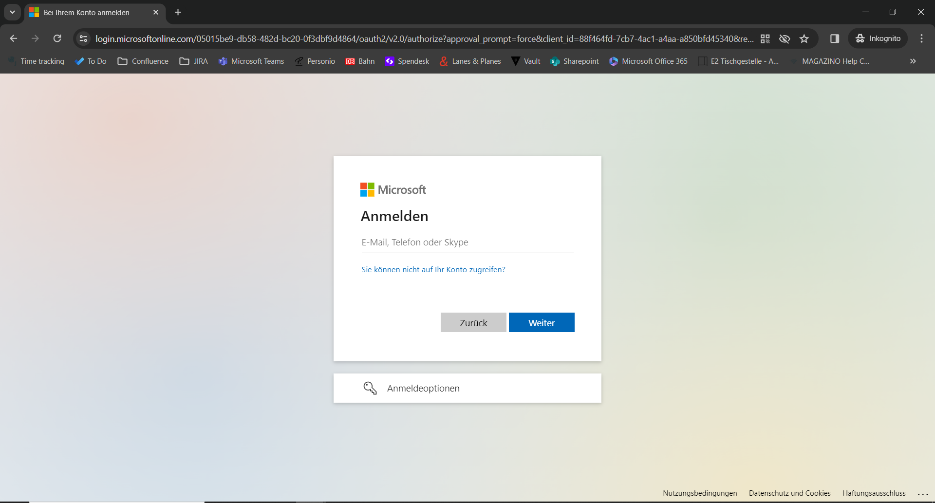
The authorized accounts for each Magazino Operations Center instance are managed by Magazino.
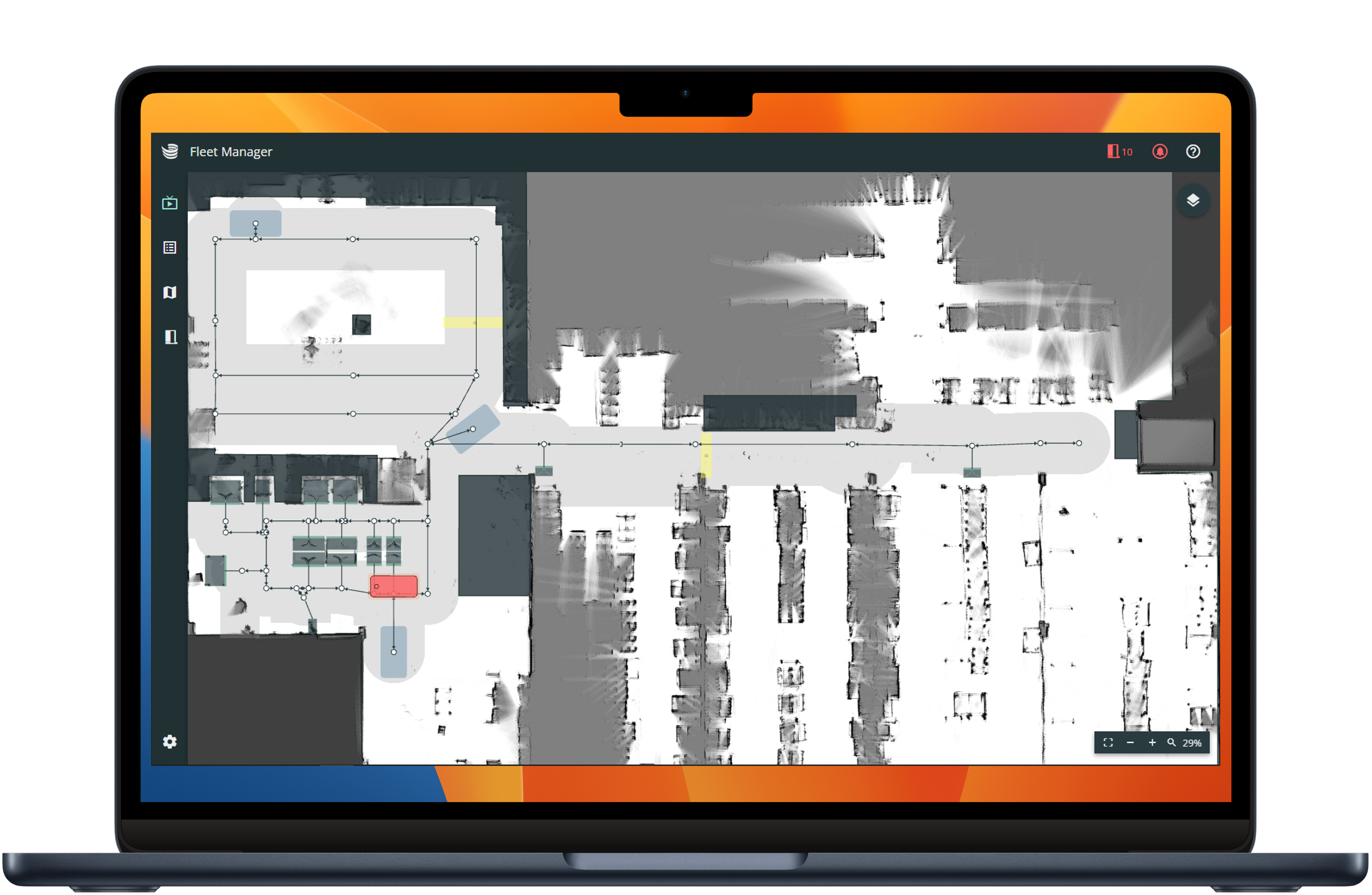
Live view
The live view allows users to monitor and interact with an active SOTO fleet.
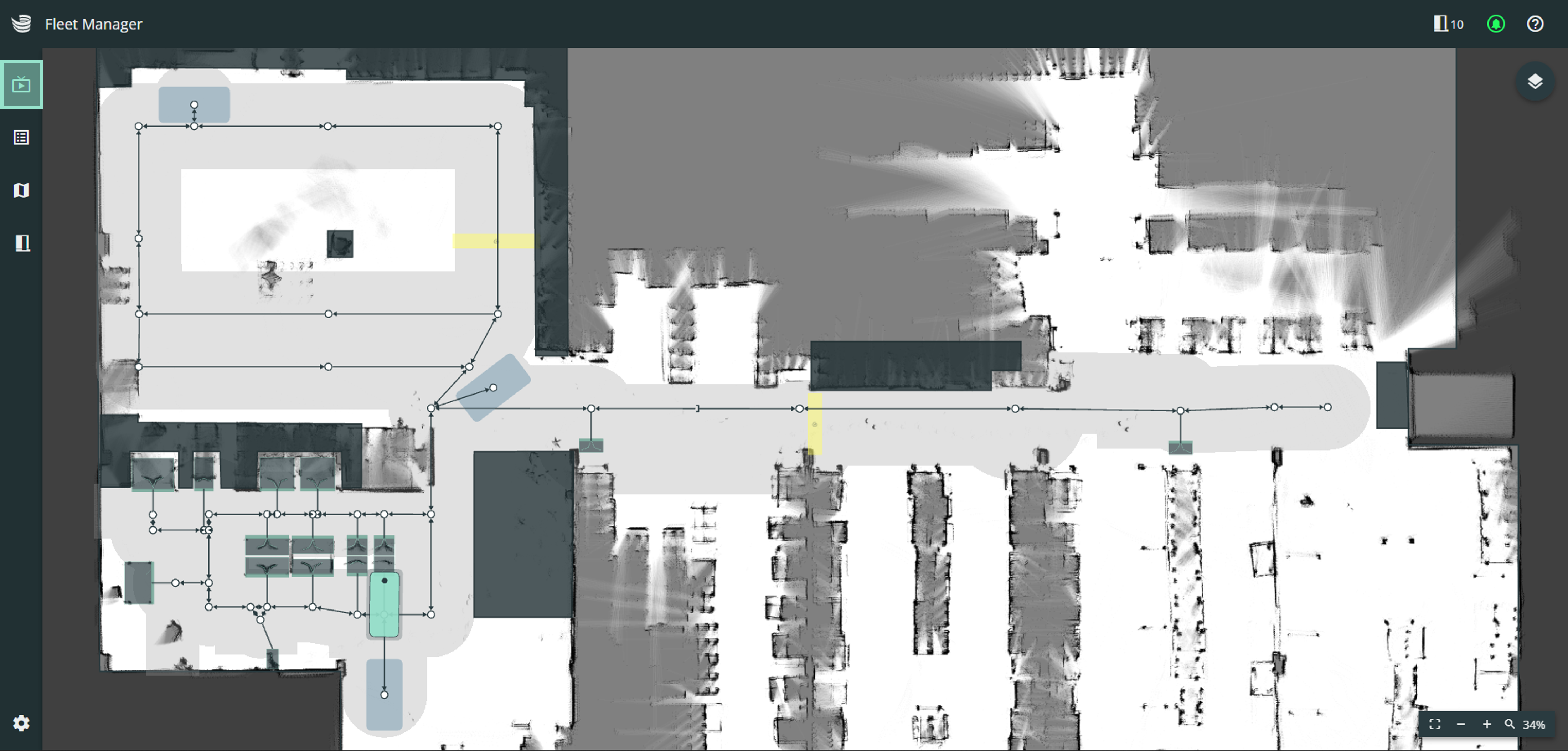
The live view provides a localization map that contains all objects added in the modelling tool. This includes obstacles, transfer stations, charging stations and the route with its edges, nodes and permitted driving areas.
The live view is the default starting page when accessing the Magazino Operations Center.
The live view provides the following features:
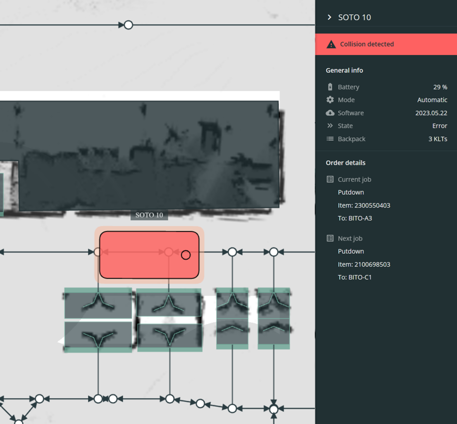
Robot Status
The status of each SOTO is shown in either red or green. If you click on the robot a detailed list of the robot’s status and debugging options is shown.
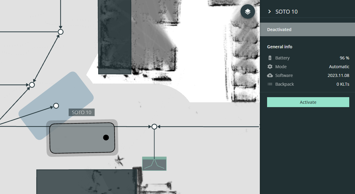
SOTO Management
Each SOTO can also be activated or deactivated.
If a robot is deactivated, it will no longer accept transport jobs and remain in its position.
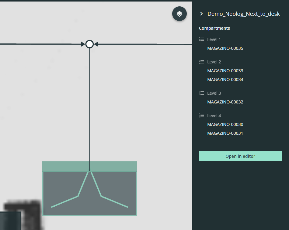
Shelf inspection
By selecting a shelf the compartment details can be inspected.
 | The customization menu can be found in the top right-hand corner of the live view. |
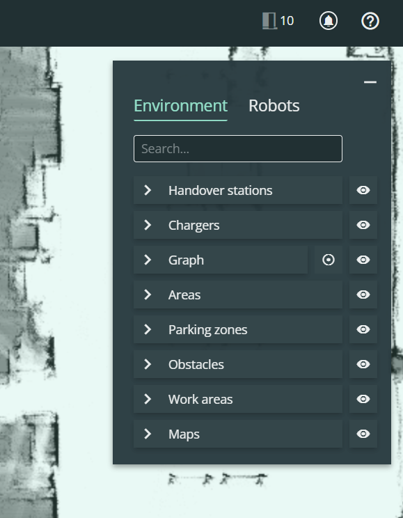
Environment
On the "Environment" tab, all available components can be viewed and the view can be customized.
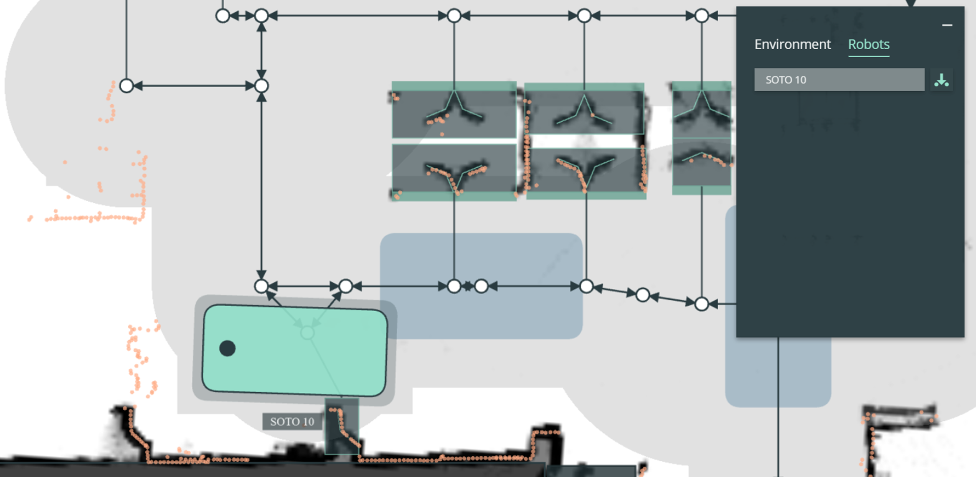
Robots
In the "Robot" tab, each connected SOTO can be checked.
You can also display the live laser scanner data for each SOTO. This is particularly helpful when troubleshooting and positioning components.
Order manager
The order manager can be used to manage and monitor transport jobs and to create manual transport jobs.
The order manager is intended to be used for setting up transport orders or to inspect current and previous orders. In a live environment, transport jobs are transmitted to the robot from the master controller and the WMS. The order manager is intended to be used during setup for test orders or to inspect current and previous orders.
The order manager is only available if also the master controller is provided by Magazino. If a third-party master controller is used, all transport jobs are displayed in that system.
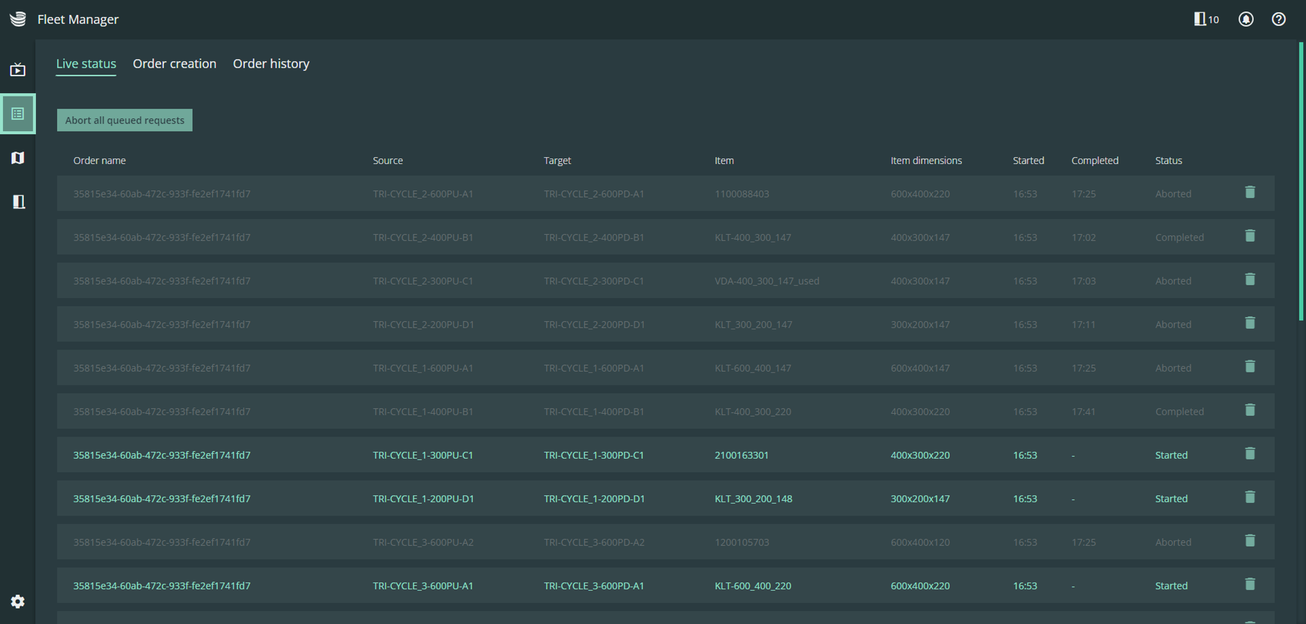
Live status
The live status shows the currently active transport job with additional information such as the source, sink and KLT dimensions.
Order creator
The order creator can be used to create manual transport jobs.
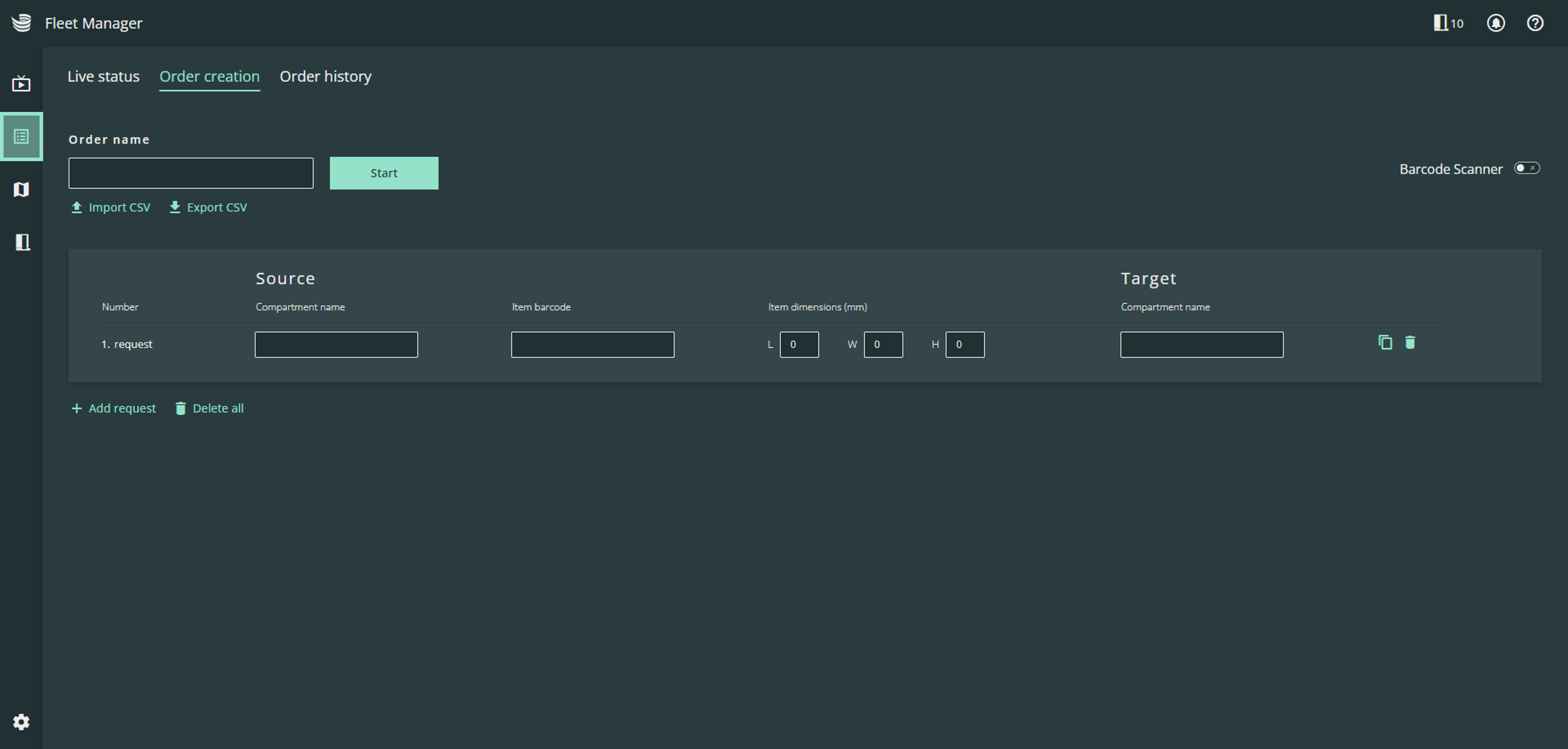
To create a transport job the following information is required:
Name (collective transport order)
Source:
Source compartment name as shown on the docking adapter
Load carrier (KLT) barcode
Load carrier (KLT) dimensions (length x width x height)
Target:
Target compartment name as shown on the docking adapter
Using a portable barcode scanner makes the order creation process much easier. If you switch the input method to barcode mode (top right-hand corner), the cursor automatically jumps to the next field after each scan.
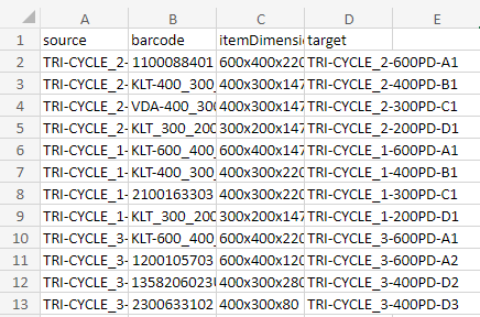
It is also possible to input a transport job as a CSV-file:
Order history
In the order history you can inspect previous transport jobs.
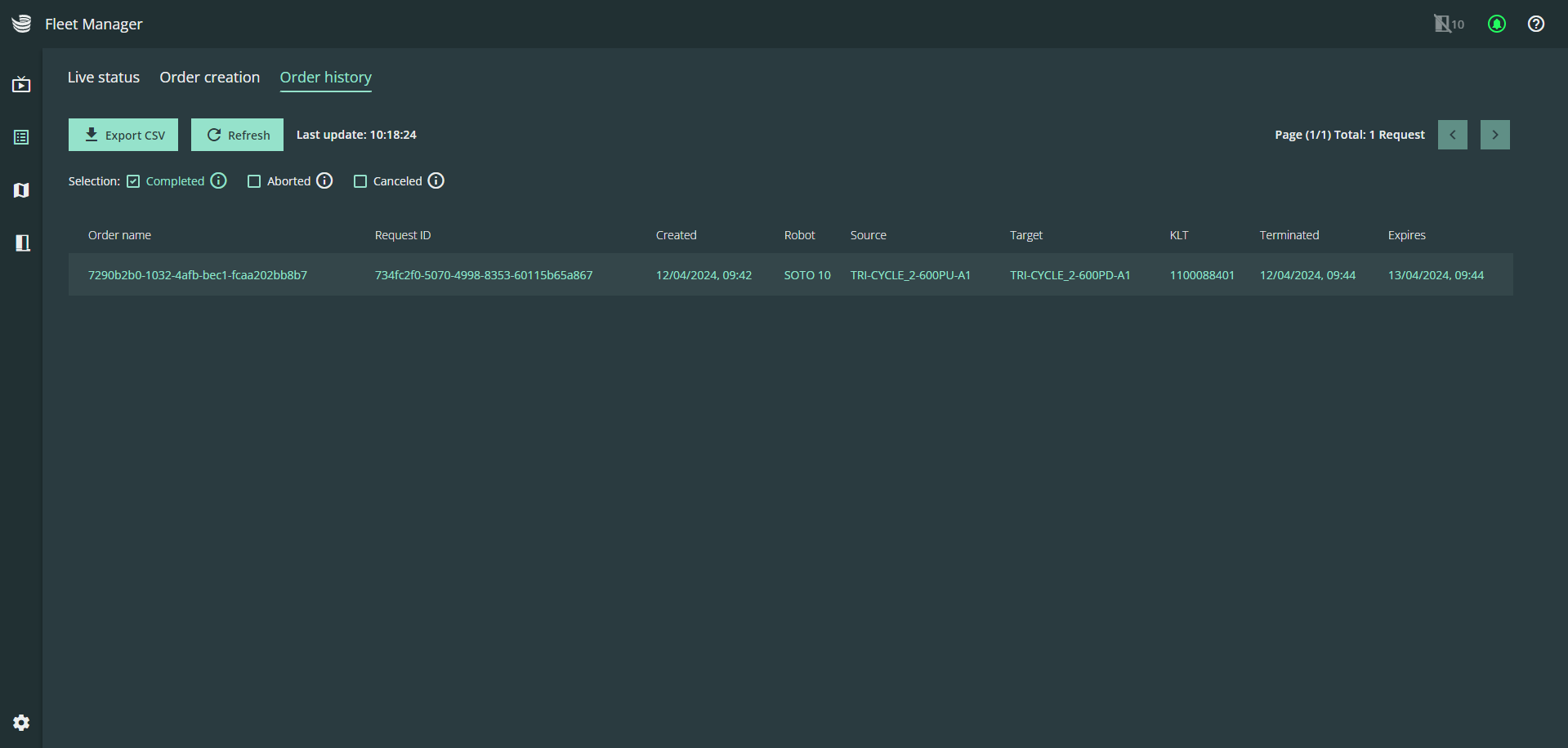
All transport jobs are automatically deleted from the order history after 24 hours.
Fleet overview
The fleet overview provides an overview of all robots that are connected to the MQTT broker. In addition, all connected robots are displayed in the header next to the SOTO icon for quick identification.
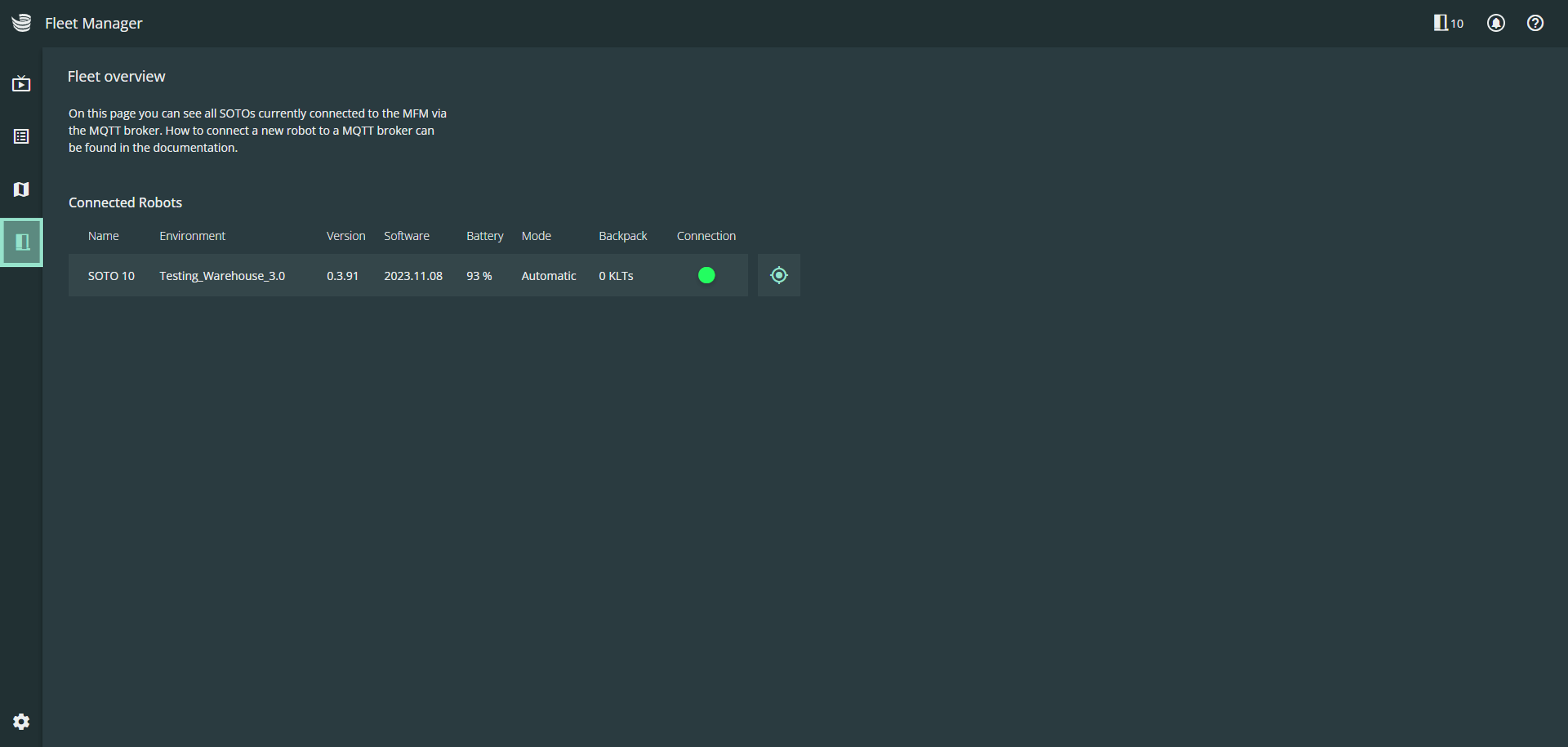
The following information is displayed for each connected robot:
The Name of the robot
The environment in which the robot is active
The version of the active environment
Battery status to check the current charge level
The operating mode of the robot (automatic, mapping or manual)
The number of load carriers in the robot's backpack
The connection status of the network connection
The synchronization of SOTO with the fleet overview can take a few seconds.
Modeling
You can create and manage environments in the modeling area.
Maps
All localization maps recorded by the robot can be found in the maps section.
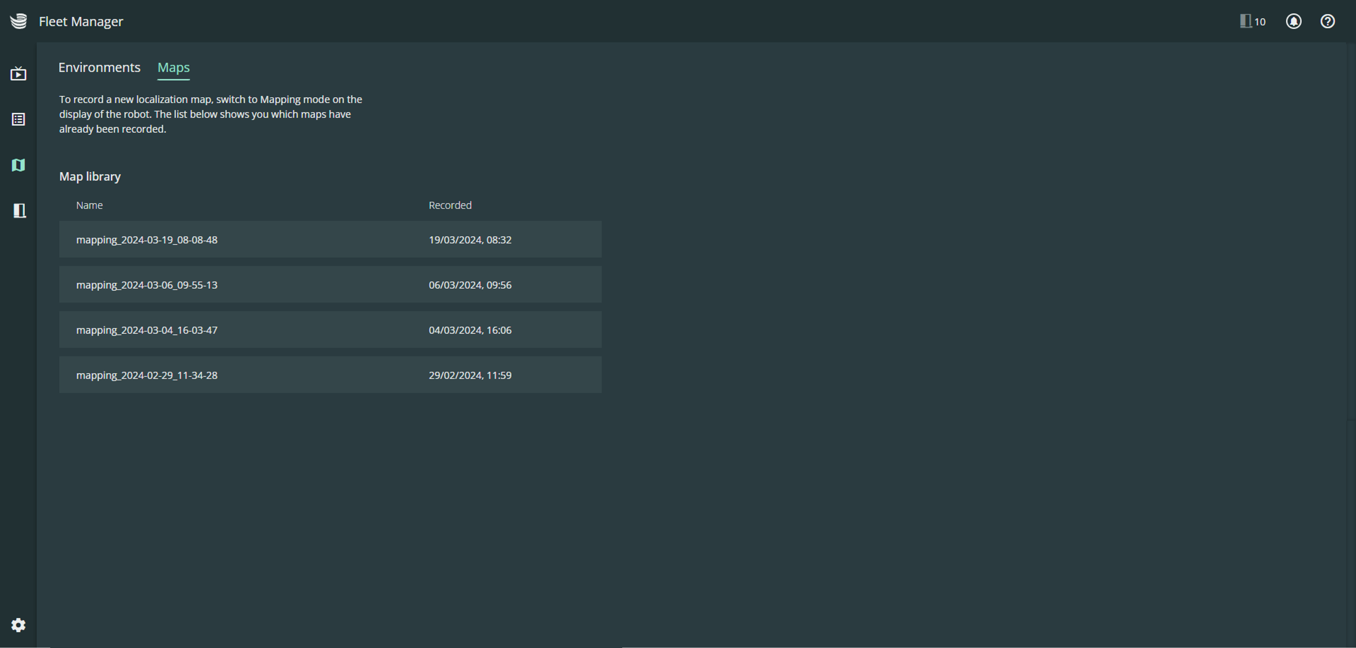
To record a new localization map, switch to mapping mode on the robot's display and use the controller to navigate the robot through the environment. The map is created and uploaded to Magazino Operations Center automatically.
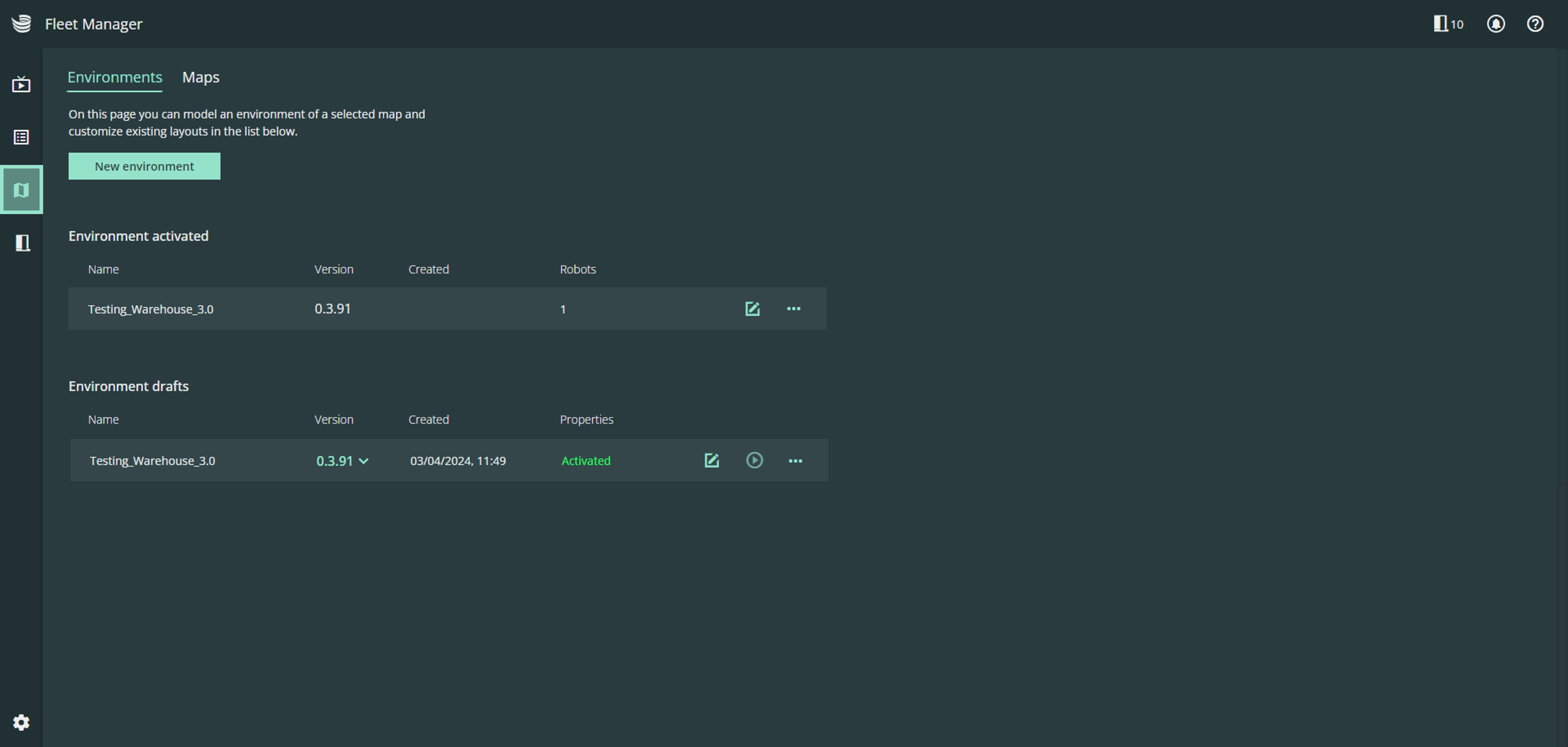
Environments
An enriched map is called an "environment". All SOTOs require an environment model to operate.
In the environments section you can find an overview of all available environments.
If modeled correctly, the environment can be activated and deployed to the SOTO fleet.
Environment editor
The environment editor can be used to create and adjust environments.

To model an environment, all shelf and compartment measurements are required - as shown below.
Creating a new environment
To create a new environment, click “New environment” and assign a name to your environment.

All environments require a background image. The background image can be either:
Image (PNG image of floorplan)
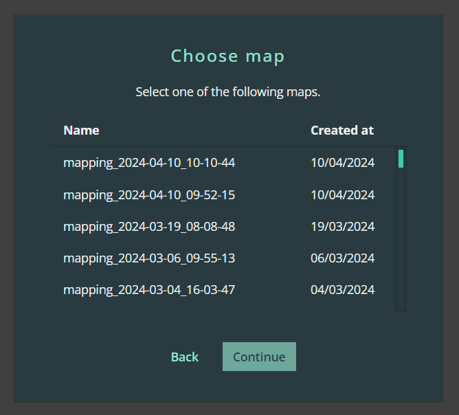
Localization map (recorded by the robot)
If you have a floorplan of the working area this can be uploaded and scale. However, it is strongly recommended to use a localization map, as this is consistent with the environment perceived by the robot.
Select the correct localization map that you have recorded via the robot from the list of maps.
If you wish to update your localization map at a later time, the map can be replaced with an updated version at any time.
The new environment will automatically open in the environment editor. You can position the map as desired in the layout.
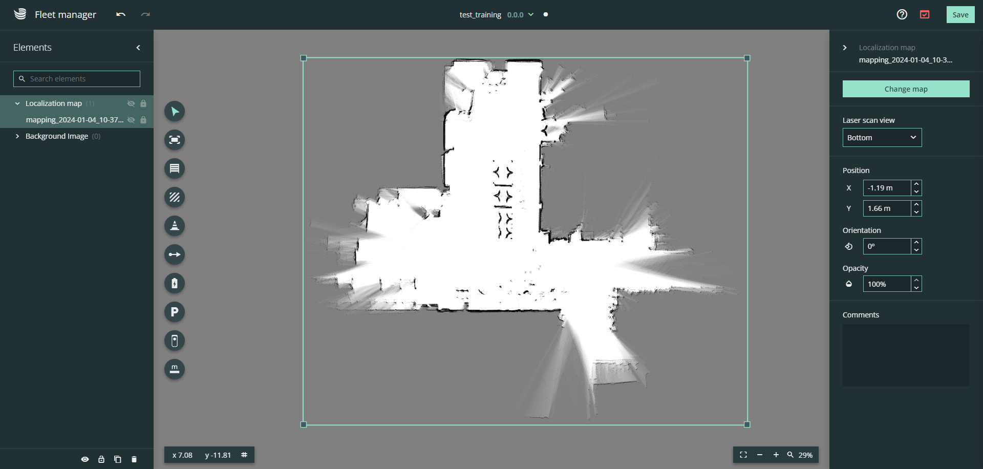
You can also adjust the position and orientation of the map in the right-hand panel.
Editing an existing environment
Select the environment you would like to edit and click the pencil symbol.
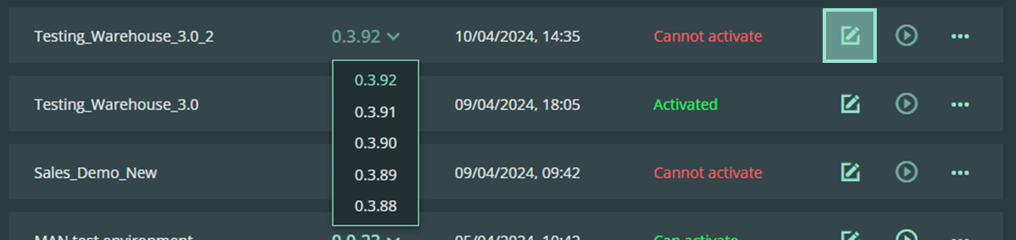
You can also edit older versions of the same environment by selecting the save file from the drop-down menu.
Toolbar
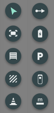
The environment editor provides a range of tools for editing the map.
The tools can be selected in the left-hand toolbar. The selected tool is displayed in green.
Selection tool
 | The selection tool allows you to select and move individual elements on the map. Hover over the cursor symbol and select the "node selection tool" i.e. the cursor with a dot underneath. |
Select nodes, edges or objects to reposition them or use the side panel for fine-grained edits.
Work area
 | The work area shows the area on the map where SOTO is permitted to move. |
The work area sets the boundaries in which the robots are allowed to move and perform tasks. This area is created as a polygon.
Press and hold the "Shift" key to lock the work area to 90° corners.
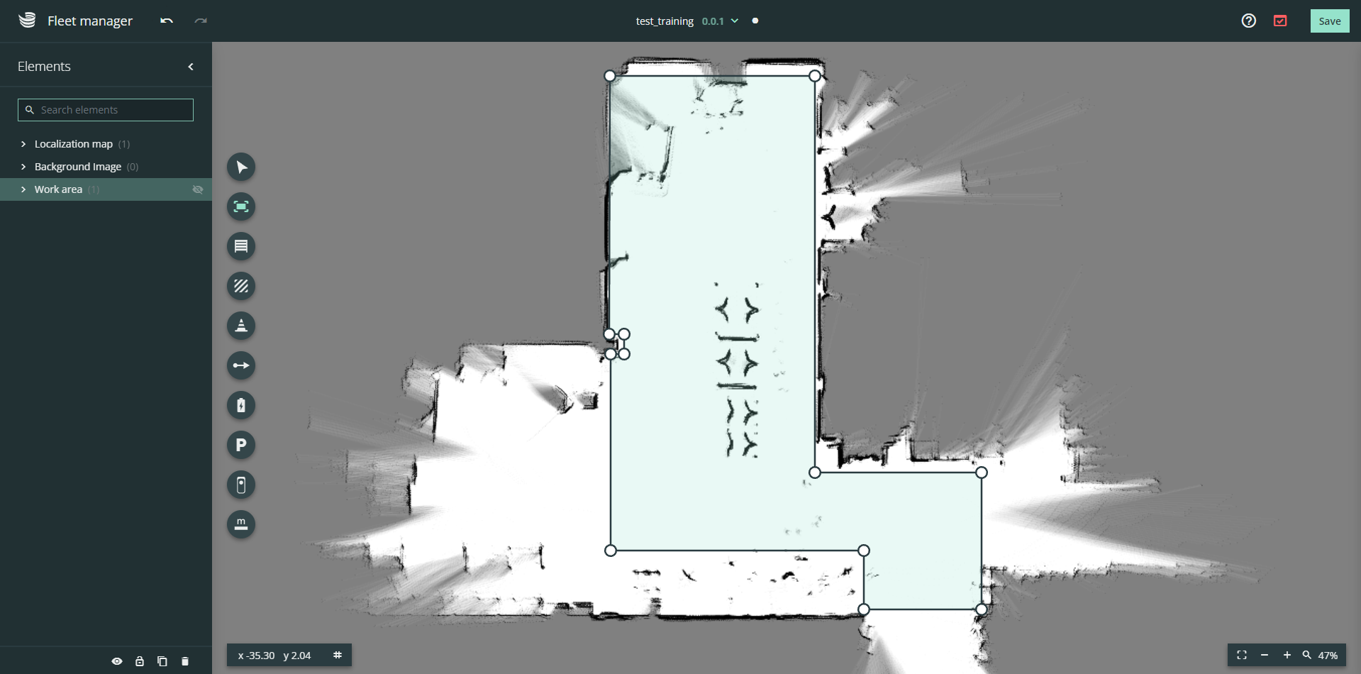
To adjust the work area, select the work area tool and drag the nodes into the desired position. To add nodes, click on one of the connecting lines.
The work area is required for a successful environment validation.
Handover stations
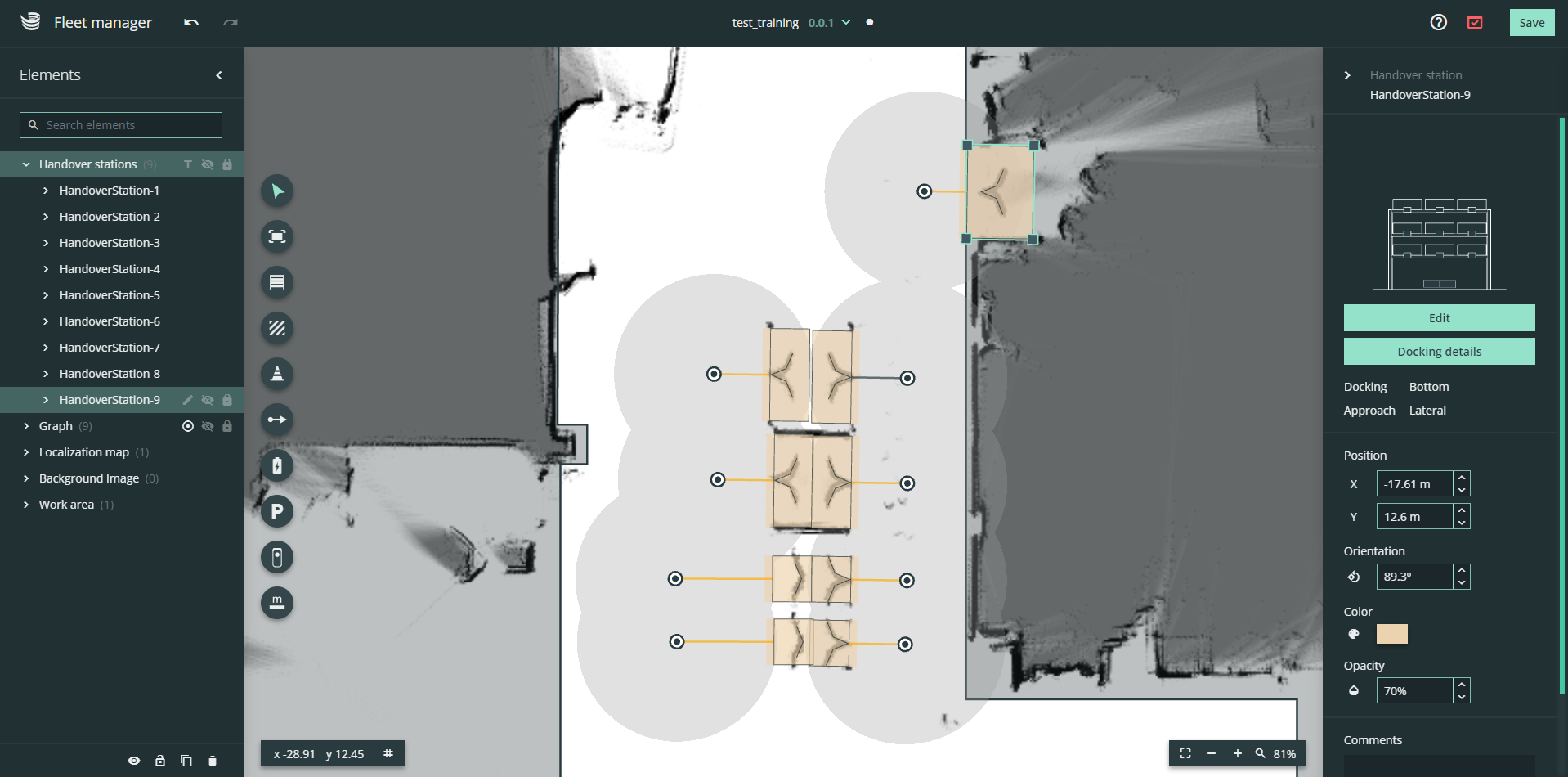
 | The handover stations are drawn on the map to show SOTO where the handover stations are located in the real working environment. |
The handover station tool opens the handover station editor. Use the handover station editor to create a model of your shelf.
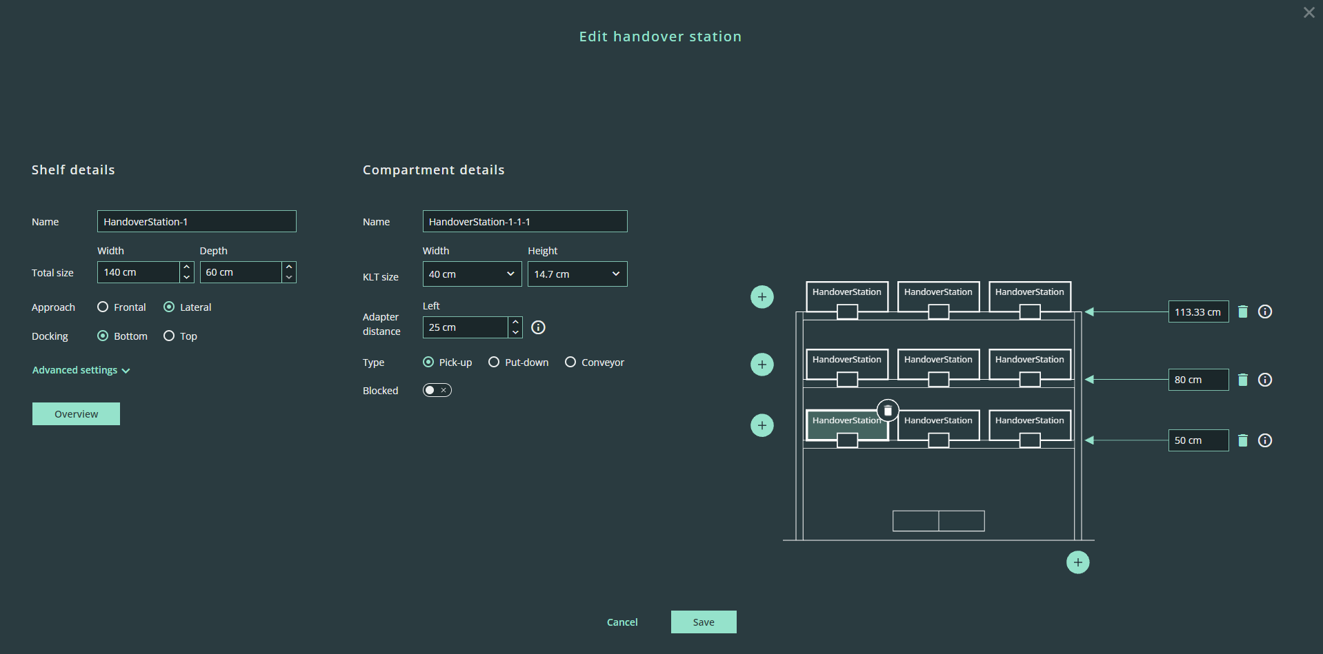
Handover station details
Name: free text
Total size: width
(Docking-) Approach: Frontal or lateral
Docking (shape position): Top or bottom docking
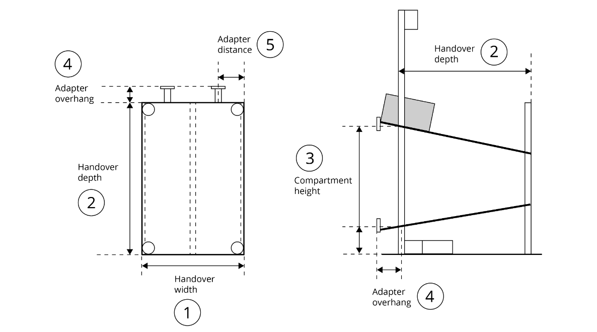
Advanced settings:
Type: Static, adjustable
Adapter overhang
Shape offset: x, y
Compartment details
Select the individual compartments in the graphic and enter the dimensions for each compartment.
Name: free text as given in the compartment adapter QR-code
Size: width
Adapter distance: Distance from the left shelf edge to the center of the compartment in cm
Type: Pick-up, Put-down, Conveyor
Blocked: temporary blockage of a single compartment
Visualisation
Height of compartment row: Height from the floor to the top edge of the shelf layer in cm.
Add compartment: “Plus” icon on the left-hand side of a row
Add column: “Plus” icon on the bottom of the visualization
Delete compartments: "Bin" symbol at the top right corner of the compartment
Delete rows: "Bin" icon next to the input field for the height of the row
To model the handover station, measure the dimensions of your shelf.
Once you have saved the shelf details, a model of the shelf is created and automatically placed in the environment. Position the shelf so that it overlaps with the docking shape on the map.
The position of the handover station must not differ by more than 20 cm from the virtual position on the map.
Model all shelves and handover stations and place them in the environment.
If you have identical shelves, you can copy the shelves with Ctrl+C → Ctrl+V to avoid having to enter identical dimensions multiple times.
Zones
 | The zones are configurable areas where specific driving speeds can be prescribed. |
Create zones and place them in the work area and set driving speed limits.
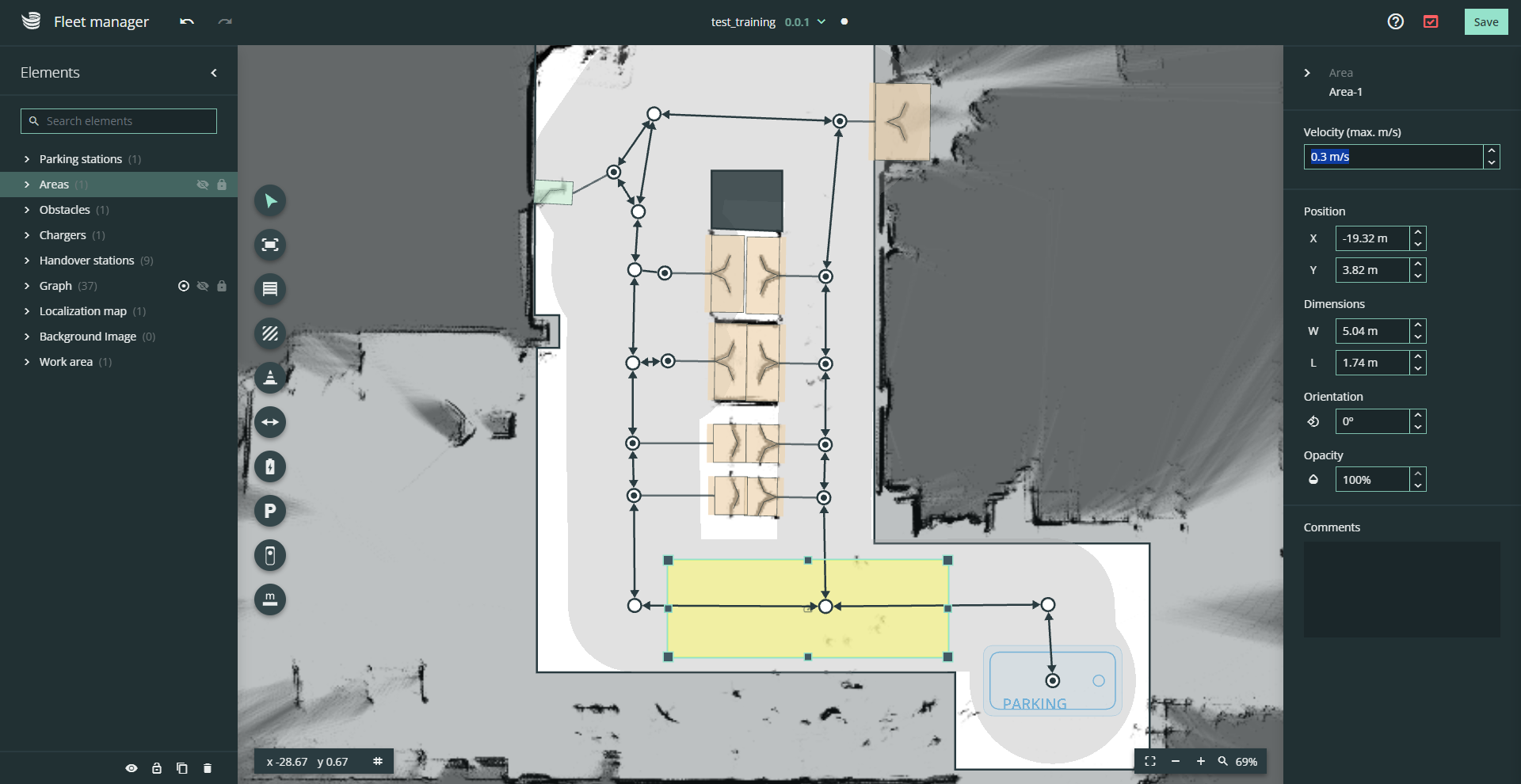
SOTO adjusts its driving speed accordingly if its footprint breaches a zone.
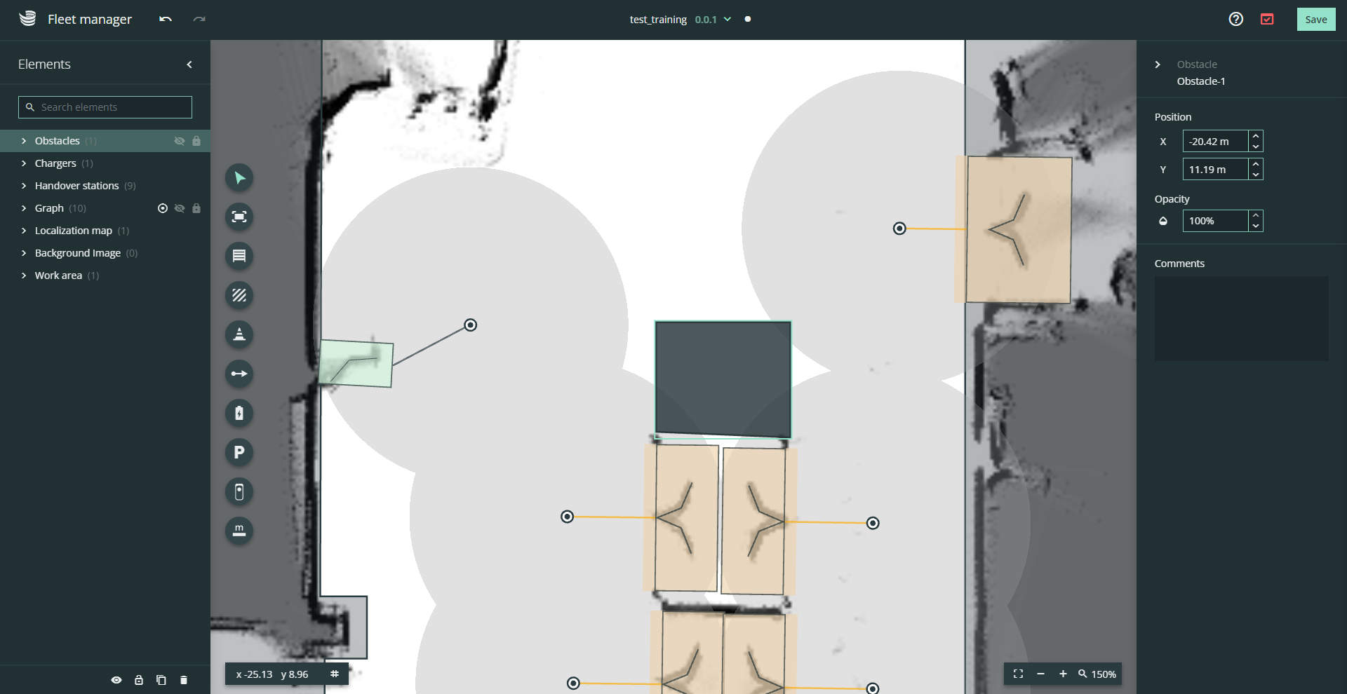
Obstacles
 | The obstacles are drawn on the map to set up areas where SOTO is not allowed to drive. |
You can create obstacles to model persistent objects or areas to be avoided within the work area. Obstacles are created as polygons.
Graph tool
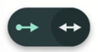 | The graph tool is used to draw travel paths for SOTO. Hover over the arrow symbol and select the two-way graph tool. |
Create the driving graph by placing a mesh of nodes and edges in the environment. Connect the nodes of all handover stations, chargers and parking zones to the driving graph.
Each edge can be selected either as a one-way or two-way driving path.
The driving graph must have the following properties:
No open-end graphs
Drivable paths between all handover stations, parking zones and chargers
Press ESC to deselect the current graph section and continue at another node.
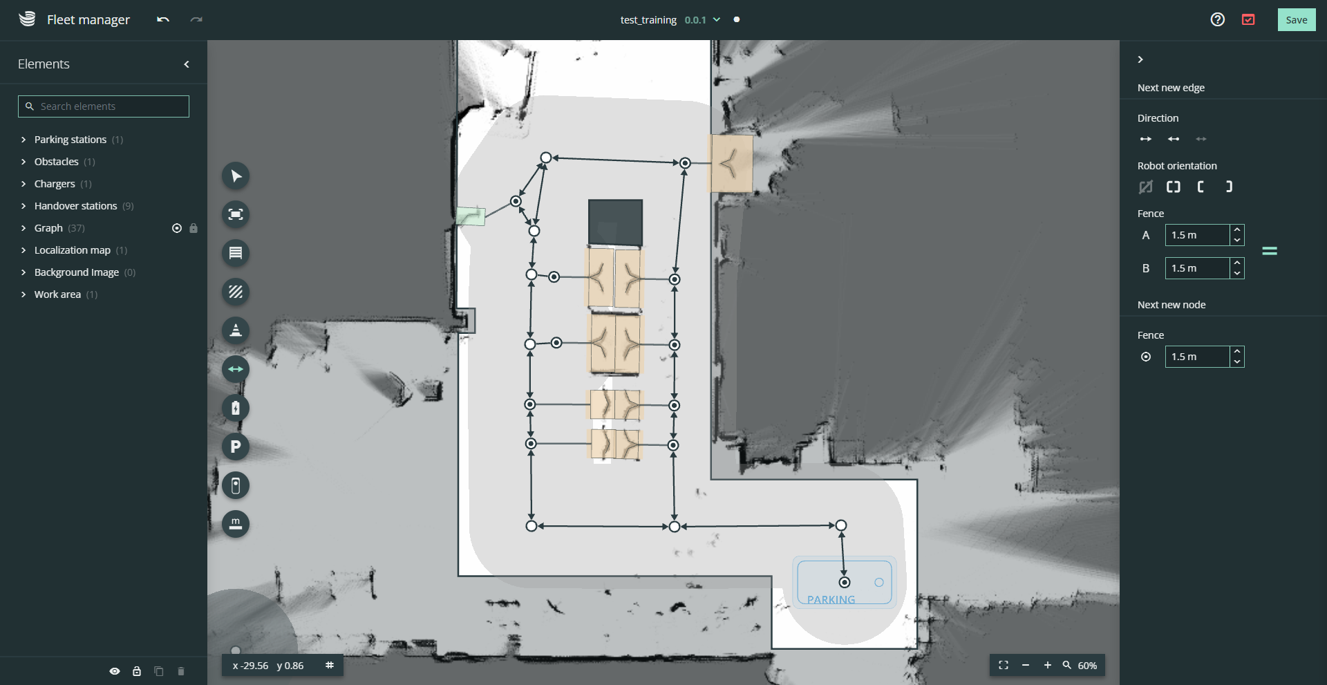
All nodes and graphs are assigned a fence property. The fence represents the area around the node or edge in which the robot may deviate from the driving graph. This is used for path optimization and obstacle avoidance.
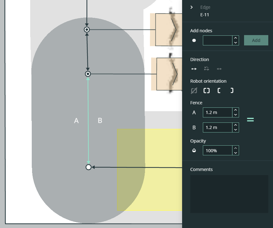
The fence limits can be made larger or smaller on each side. This determines the robot’s navigation path around obstacles, favoring either left or right.
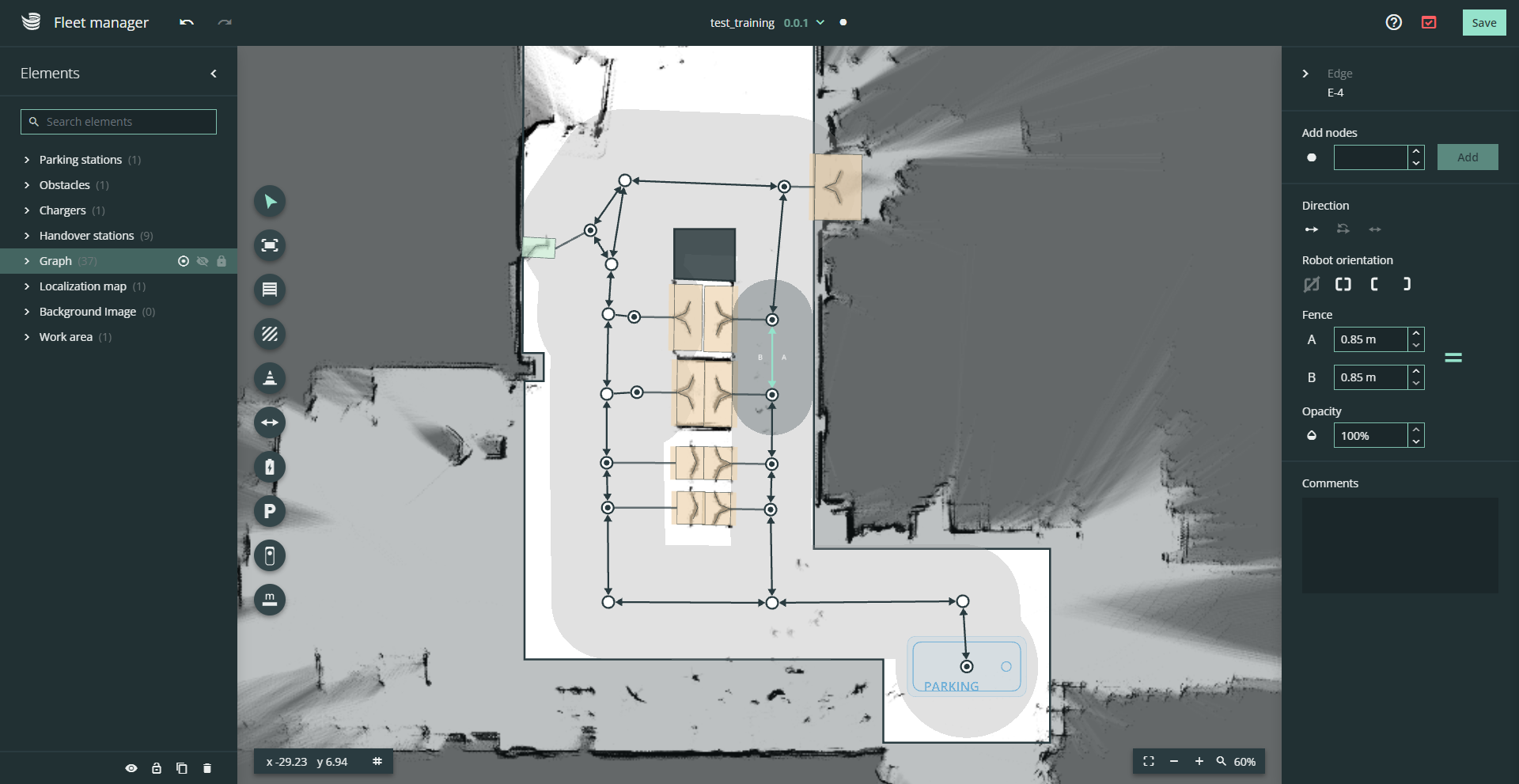
Make sure to reduce the fence limits to the actual available space to improve the robot's path planning performance. With correct modeling, SOTO will plan its path in the best possible way and require fewer path corrections.
Pay attention to possible turning points when defining the fence limits for nodes and edges.
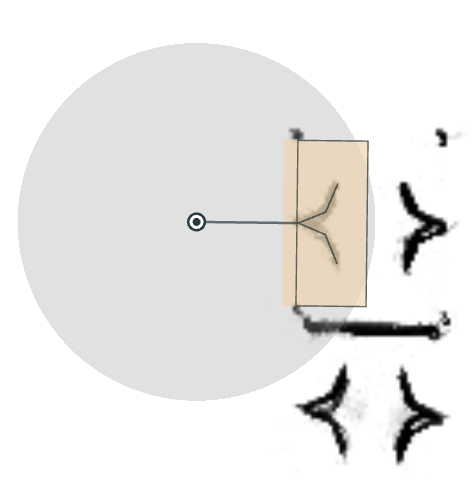
Chargers
 | The chargers must be placed on the map to show SOTO where the charging stations are located in the real working environment. |
You can position the chargers by overlapping the virtual model with the 135° angle of the charger body.
The charger must be connected to a node on the driving graph. The seven-digit serial number of each charger must be entered for a plausibility check during relocalization. This can be found on the nameplate of the charger.
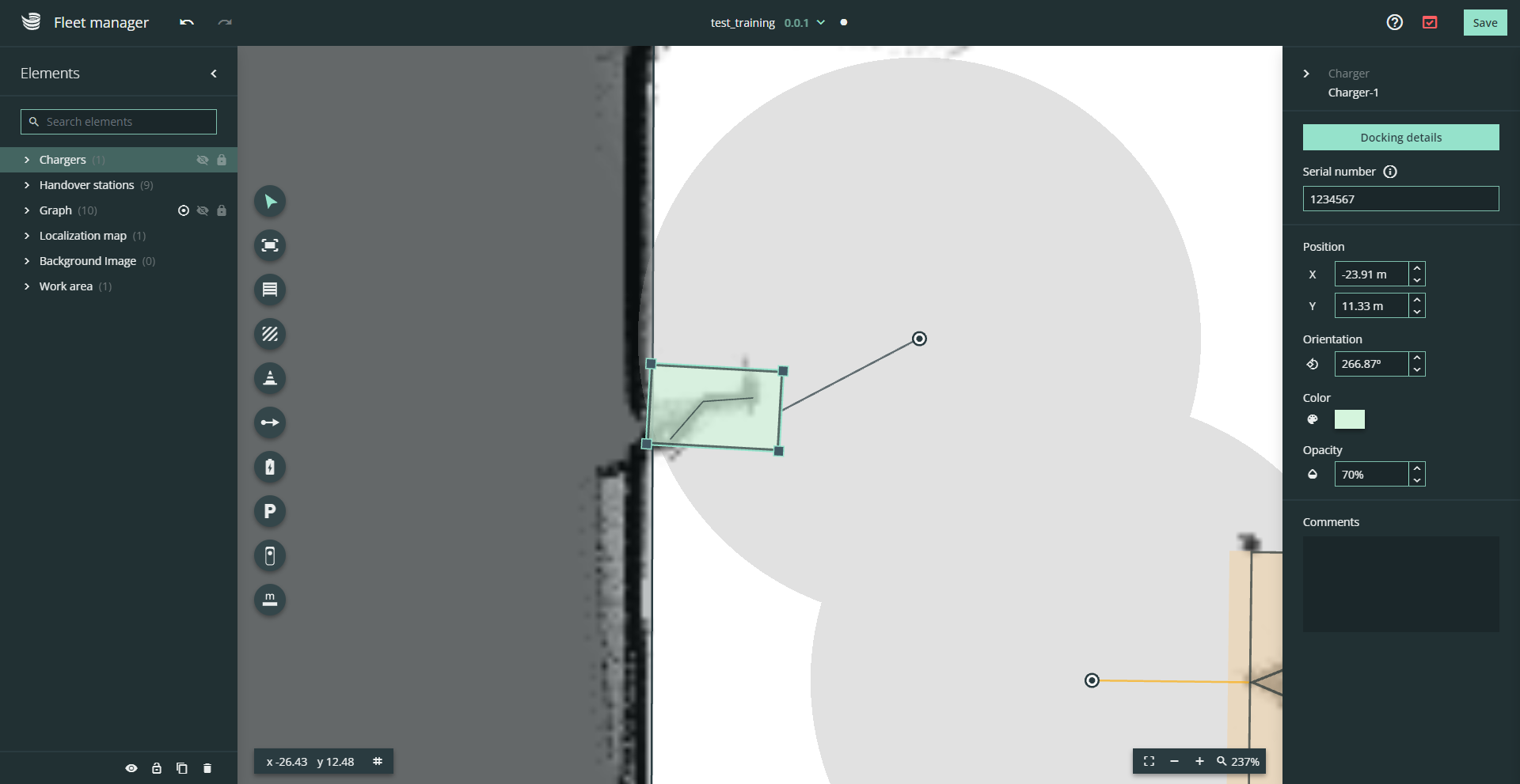
The position of the charger must not differ by more than 20 cm from the virtual position on the map.
At least one charger is required for a successful environment validation.
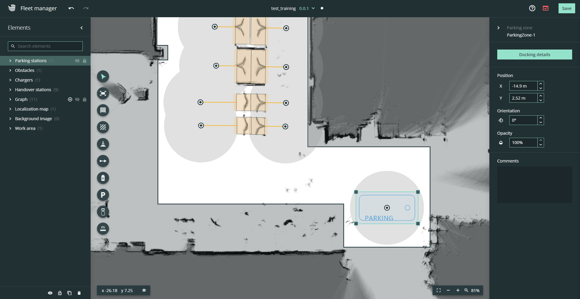
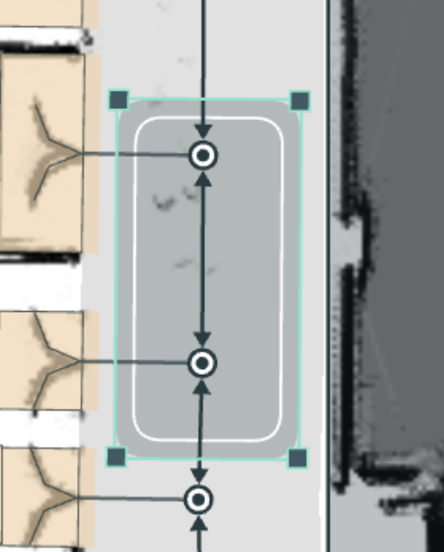
Parking zones
 | The parking zones are drawn on the map to show the robot where it is allowed to stand when there are no tasks. |
Add parking zones to the layout and connect them to the graph.
SOTO will wait at the parking zones if there is no active transport job. SOTO also automatically returns to the nearest parking zone in the event of a fire alarm.
At least one parking zone is required for a successful environment validation.
SOTO guide
 | The SOTO guide serves as a tool for test driving areas with a scaled SOTO model. |
Place and move the SOTO model along the driving graph of the layout.
The purpose is to check the SOTO space requirements in the layout.
Measurement tool
 | You can use the measuring tool to determine the distance between two objects. Select the measuring tool, then click on one point and again on a second point to measure the distance. Deactivate it by selecting another tool. |
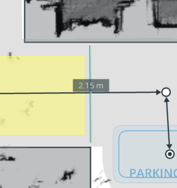
Draw measurement lines in the layout to view its length.
Saving and deploying an updated environment
Once modelling has been completed the environment can be validated, saved and deployed to SOTO.
Validation
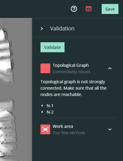
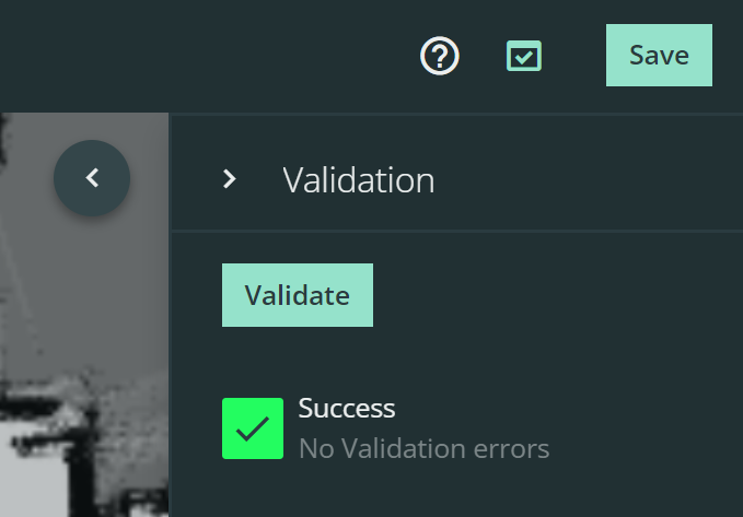
It is only possible to deploy environments to SOTO that have been successfully validated. The validation menu and the error overview are located next to the "Save" button.
Each validation error is displayed in the validation menu. Try to fix the issue and restart the validation to see the updated result.
You can still save a unvalidated environment, but it is not possible to activate it.
Versioning
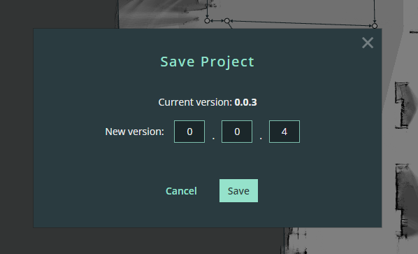
Save a new version of your environment.
It is not possible to overwrite an old version of an environment. Each increment has to be saved as a new version.
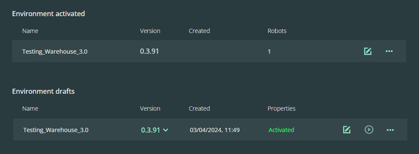
Deployment and activation
Once the environment has been saved, it will be displayed in the environment overview.

Select the correct version of your environment and activate it by pressing the play button.
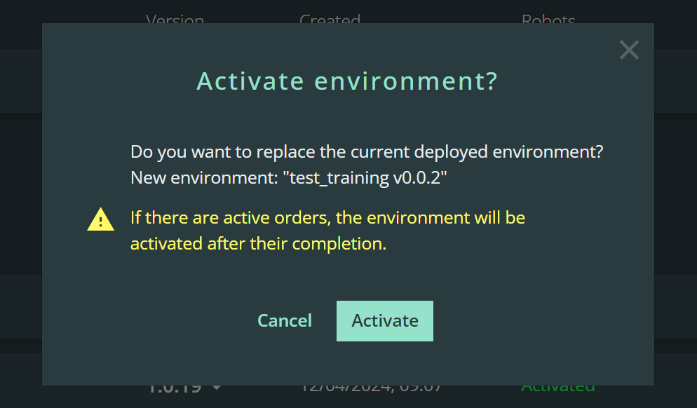
When activating a new environment, all currently active orders are completed before the new environment is activated.
In the event that SOTO becomes delocalized in the new environment, it has to be manually driven to a charger before automatic operation can resume.